How to Control Power To a Sensor with a Microcontroller
We often get the question of how to control power to our sensors from users who want to read and control the sensors using their own microcontroller board, such as an Arduino. This article will tell you how to create a small 3 part circuit which will allow your microcontroller to turn on or off power to a sensor, using a single IO pin. Turning off the power to sensors is critical for low power battery applications.
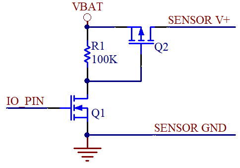
The circuit below uses two MOSFET transistors. The N-Channel transistor Q1 is turned on when the IO pin goes high, which drives the gate of the P-Channel transistor Q2 low turning it on, passing voltage from the battery to the sensor. When the IO pin goes low, Q1 turns off, and the gate of Q2 goes high, turning off the transistor, blocking voltage from the battery to the sensor.
Make sure that the P-Channel MOSFET is rated for more current than the sensor consumes. For example, if you are powering a single VH400 sensor, make sure that the transistor is rated for 12mA or higher, which is nearly every transistor on the planet. Also Make sure your battery voltage does not exceded the maximum gate to source voltage Vgs(max). This is typically 20V for most transistors.
Most sensors need to be powered on for a few seconds before taking a reading. This is called sensor "warm-up time". For example, the VH400 should be powered for about 1 second so that the output has time to settle.